
- Product Categories
- Pneumatic control valve
- Electric control valve
- Special regulating valve
- Quickly shut off the valve
- Self - operated pressure regulating valve
- Pressure relief valve

Sales Phone:
0577-67362106
Fax:
0577-67362106
Sales Manager:
叶喜娇 13968983278
13989720218
Technical Consulting:
叶向春 13989720218
Q Q:
1148499103
Mail:
1148499103@qq.com
Address:
Oubei Town Dong Ou Industrial Zone, Wenzhou City, Zhejiang Province
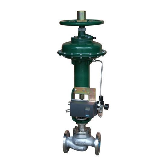
KLP series of pneumatic fast mounted single seat control valve
Hits:2920 Update time:2017-05-10
Introduction
KLP series of pneumatic quick-mounted single-seat control valve with top-oriented unbalanced structure, high strength, heavy load, S streamlined channel, the pressure drop is small, large flow coefficient, adjustable wide range of high precision flow characteristics. The control valve for heavy load, ordinary or harsh conditions, close tightly, adapted to a variety of pressure and temperature of the fluid or gas control, adapt to a variety of actuators, from the regulatory role. The quick-release valve cage is designed to reduce the lateral load and spool vibration, reduce friction, and extend the service life of the control valve. Flow open design, medium flow tends to control the direction of valve opening, small flow state controllability is good. According to the working conditions can choose to reduce noise, anti-cavitation of the special cage.
Product specification
Specification Name Industrial Control Valve Structure Length Flange Standard Pneumatic Regulator Pressure Level
International Standard IEC 60534-1 IEC 60534-3-1 ASME B16.5 IEC 60534-4 ASME B16.34
National standard GB / T17213 GB / T17213.3 JB / T79, HG / T20592 GB / T4213 GB / T9131
Main parameters of the valve body
Form top-through straight seat valve
Nominal diameter DN20 ~ DN300
Nominal pressures PN16, 40, 63, 100, ANSI CL150, 300, 600
Body cover material WCB, WC6, WC9, CF8, CF8M, HC276, Ti alloy, etc.
Trimmer material 304,316, HC276, Ti alloy and so on
Filled PTFE V-shaped, flexible graphite, PTFE packing, flexible graphite clip nickel wire
Actuator pneumatic, electric, hydraulic
And actuator connection bolt compression type, round nut lock type
Bonnet type Standard type, high temperature type, low temperature type, bellows type
Connection type Flange type (RF, MFM, RJ), welding type (SW, BW)
The flange is as follows
Working temperature -29 ~ +230 (standard), +230 ~ +560 (medium temperature), - 30 ~ -196 (low temperature, ultra low temperature)
Leakage Level ANSI B16.104 IV, VI, Zero Leakage
Flow characteristics such as percentage, linear, switch
Inherent adjustable ratio of 50: 1
Valve structure length (flange distance)
Nominal diameter 20 25 32 40 50 65 80 100 125 150 200 250 300
Flange from L PN16, 25 184 184 200 222 254 276 298 352 410 451 543 673 737
PN40 194 197 210 235 267 292 317 368 425 473 568 708 775
PN63,100 206 210 220 251 286 311 337 394 440 508 610 752 819
Rated flow coefficient and stroke
Nominal diameter 20 25 32 40 50 65 80 100 125 150 200 250 300
Seat diameter 20 25 32 40 50 65 80 100 125 150 200 250 300
Rated Cv Linearity 7 14 20 30 44 68 110 175 275 440 690 1000 1600
Equal percentage 6.3 10 17 25 40 63 99 160 250 360 640 900 1440
Rated travel 16 25 40 60 100
Note: DN250 and DN300 recommended the use of balanced cage valve, the use of small pressure can choose a single seat valve (detailed inquiry company technical service center)
Seat diameter 20mm below See the small flow valve manual
Installation Precautions
The new design and installation of the control system, in order to ensure that the control valve in the car to work properly, and make the system safe operation, the new valve before installation, should first check the valve nameplate logo is consistent with the design requirements. The following items should also be commissioned: basic error limit; full trip deviation; hysteresis; dead zone; leakage (in demanding cases).
If the original system of the control valve overhaul, in addition to the above items for verification, but also the old valve stuffing and connection and other parts of the sealing check.
In the use of control valve, many are often not due to the quality of the control valve itself, but the improper use of the installation of the valve caused by, such as the installation environment, improper installation location and direction or the pipeline is not clean and other reasons. So the control valve in the installation of the use of attention to the following aspects:
(1) regulating valve is a field instrument, the ambient temperature should be in the range of -25 ~ 60 ℃, relative humidity ≤ 95%. If it is installed in open air or high temperature occasions, should take waterproof, cooling measures. In a place where there is a source away from vibration sources or increase anti-vibration measures.
The following are the same as the "
(2) regulating valve should be installed vertically, in particular, can be tilted, such as the tilt angle or the valve itself is too large when the weight of the valve should be increased support.
The following are the same as the "
(3) the installation of the valve control valve is generally not too far from the ground or the floor, the pipe height greater than 2m should try to set the platform to facilitate the operation of hand wheel and easy maintenance.
The following are the same as the "
(4) the control valve should be installed before the pipeline cleaning, remove dirt and welding slag. After installation, in order to ensure that no impurities remain in the valve body, the valve should also be cleaned again, that is, access to the media should make all the valve open, so as not to impurity stuck. After using the handwheel mechanism, it should be restored to the original neutral position.
The following are the same as the "
(5) In order to make the control valve in the event of failure or maintenance of the production process can continue, the control valve should be bypassed pipeline, but also should pay special attention to the installation of the valve position is consistent with the requirements of the process.
The following are the same as the "
(6) The electrical installation of the control valve shall be carried out in accordance with the relevant electrical equipment construction requirements. If the flameproof products should be "explosion hazard electrical equipment installation specifications" requirements for installation. In the use of maintenance, in the explosive place is strictly prohibited to open the lid and repair the surface of the explosion. At the same time in the disassembly do not knock or scratch the exposed surface, after repair to restore the original explosion-proof requirements of the state.
The following are the same as the "
(7) after the implementation of the agency should pay attention to refueling lubrication, low-speed motor generally do not wash and refuel. After assembly should also check the valve position and valve opening indicator is consistent.